This technique is a recent development (see van Langenvelde and Cotton 1990, Cornwell et al. 1991, and Sault 1993). In spectral-line work, the bandwidth is generally fairly narrow, such that an acceptable approximation to the continuum emission is a linear function of frequency at each point in the image.
Each visibility consists of measurements in a band of frequency
channels. The value of the visibility at each channel is one sample of
the Fourier transform of the image. At the centre of the band
(frequency ![]() ) we sample the Fourier transform at the location
) we sample the Fourier transform at the location
![]() ; recall in one dimension,
; recall in one dimension, ![]() .
However, as the frequency changes up and down the band, we move radially
away from
.
However, as the frequency changes up and down the band, we move radially
away from ![]() in the (u,v) plane.
in the (u,v) plane.
Because Fourier Transforms are linear operators, the visibility can also be approximated by a linear function with frequency (the continuum) with the spectral-line superposed on top, provided the visibility function changes only slowly across the bandwidth. We can then fit (by least squares) the continuum-only channels with a linear function. We fit the real and imaginary parts separately, and each visibility is fitted and subtracted independently. This procedure is very fast and requires very little user intervention, apart from working out which channels contain continuum. In general, it is better to fit to the real and imaginary parts than to fit to the amplitude and phase as the whole process remains linear. The non-linear fit to amplitude and phase couples the errors on all sources and also produces an amplitude bias at low signal-to-noise ratios. Also, the more line-free channels you have, the better the fit tracks the continuum.
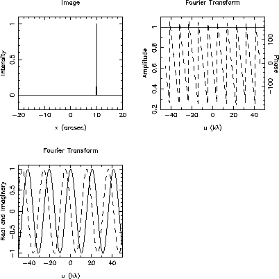
As an example, consider, in one dimension, a point source offset from the phase centre. The visibility, as a function of spacing, is a constant amplitude and a linearly varying phase. Alternatively, the real and imaginary parts are sinusoids with spacing. This is demonstrated in the following figures which show the image, and the Fourier Transform. Because u varies linearly with frequency, you can think of the abcissa as reflecting a change in frequency or a change in telescope spacing (I have assumed that the spectral index is zero). Clearly, if the change in frequency across the band is sufficiently large, you will sample a significant fraction of a period of the real and imaginary sinusoids, such that the linearity assumption is invalidated.

Figure 1: Point source and Fourier Transform
To clarify this, consider some pseudo ATCA data for two offset point
sources. I will use a typical spectral-line setup of five antennas in a
3-km configuration, ![]() GHz,
GHz, ![]() MHz, and 256
channels. In this case, the sysnthesized beam is
MHz, and 256
channels. In this case, the sysnthesized beam is ![]() arcsec.
arcsec.
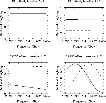
The next figure shows spectra for two point sources (upper panel offset 10 arcsec from phase centre, lower panel offset 1750 arcsec from phase centre) from one 10 s integration and for the shortest (1-2; 183 m) and longest (1-5; 2983 m) baseline.

Figure 2: Fourier Transforms of Offset Point Sources
For the source that is only 10 arcsec from the phase centre, the assumption that the real and imaginary parts of the visibility are linear functions of frequency is a good one. However, for the distant point source, the longest baseline clearly exhibits non-linear visibilities. I leave it as an exercise for the reader to work out why the short baseline is less affected than the long baseline.
Like all methods, this one cannot be used blindly, but the restrictions
are simple. Clearly, as the figures show, the approximation that the
visibility is a linear function with frequency will break down if the
visibility function varies too quickly as a function of radial distance
in the (u,v) plane (i.e. with frequency). This means a restriction
on the field of view that you can image well. Sault (1993) shows that
for a point source of brightness S Jy at location ![]() (with
respect to the phase centre), the residual continuum following a first
order fit is given by
(with
respect to the phase centre), the residual continuum following a first
order fit is given by
![]()
where ![]() is the total bandwidth, and
is the total bandwidth, and ![]() is the FWHM of
the synthesised beam.
is the FWHM of
the synthesised beam.
You might like to be aware that the MIRIAD task that implements these ideas can in fact fit higher order polynomials than first (removing the need for the linearity of the continuum with frequency assumption). This allows you to subtract the continuum more accurately at larger distance from the phase centre than the first order fit. There is also a MIRIAD task that produces an error image as well to help you assess the reliability of the fit. See the MIRIAD manual and the paper by Bob Sault for more information.
The fact that the residual continuum is a function of the distance of the point source from the phase centre should not be a surprise. As (u,v) coordinate is proportional to frequency, the channels in a visibility spectrum are sampling slightly different locations in the (u,v) plane. For a point source (which we assume to have a spectral index of zero, for simplicity) will have a visibility function whose real and imaginary parts are sinusoids. The fraction of a period of this sinusoid contained within the (u,v) coordinates spanned by a visibility spectrum will be directly proportional to the distance of the point source from the phase center. The further the point source is from the phase centre, the greater proportion of a sinusoid period is present in the visibility spectrum, and the poorer the approximation of the visibility spectrum by a low order polynomial.
This method of subtraction has the advantage over other approaches that it is generally more robust to a large variety of systematic errors (such as antenna gain errors). It also copes with continuum emission that has a non-zero spectral index, is much cheaper computationally and much easier to use than the other methods.
Now let us continue with the implentation of this method in AIPS. There are three choices, UVBAS, UVLIN, and UVLSF. In standard AIPS, UVBAS should be avoided, as it fits to the visibility amplitude and phase (see the discussion above). The ATNF version has been changed to fit real and imaginary, but to avoid confusion, I suggest you keep clear of UVBAS. The tasks UVLIN and UVLSF have basically the same functionality, but differ slightly in their packaging. UVLSF has the advantage that it can output the fit into a separate data base, which you can then image. This gives you an excellent indication of how the method has performed, as well as providing you with a good continuum image. On the other hand, UVLIN offers more flexibility when selecting the continuum channels, plus a useful shifting option (see below). I will show example adverb boxes for them both.
Both UVLIN and UVLSF will work on multi- or single-source files. However, there are no source selection adverbs, and more importantly, you can't apply the FG table so that bad channels within the range you designate as line free cannot be excluded easily from the fit. Thus, you should probably SPLIT the desired source into a single-source file (see § 12) first, applying all calibrations and flags.
Note however, that you may want to run CVEL (offline Doppler tracking; see § 13.5) and there are some advantages to doing this on a multi-source file. Countering this is the fact that you are best subtracting the continuum before running CVEL if the continuum is strong and the continuum subtraction programs are really aimed at single-source files !! Good design isn't it ? See the extra discussion in § 13.5 for more help.
UVLSF is fairly straightforward to use.
| UVLSF | |
| inname,inclass | Input visibility |
| inseq,indisk | file |
| outname,outclass | Output subtracted |
| outseq,outdisk | visibility file |
| bchan=1 | Write all channels to the |
| echan=0 | output subtracted file |
| chansel=5,30,1 | Select groups of continuum channels |
| to fit (start, end, increment) | |
| dooutput=1 | Write the fit into an output file |
| channel=128 | Select a channel at which to compute |
| the continuum fit | |
UVLIN is not quite so straightforward, as it offers more flexibility with regards continuum channel selection. It can also be used to flag channels as bad, based upon their discrepancy from the fit rather than subtracting the fit.
Obviously, there is not much point to flagging data after the fit and subtraction; the fit would have been biased already. The flagging option should be used in conjunction with docont=1. This tells UVLIN to retain the continuum rather than subtract it, so that the output data-base contains all the data with the bad channels flagged (the weights will be set negative).
| UVLIN | |
| inname,inclass | Input visibility |
| inseq,indisk | file |
| outname,outclass | Output subtracted |
| outseq,outdisk | visibility file |
| infile='AREA:WEIGHTS' | Specify a file with the |
| the weights for each channel | |
| nboxes | Specify number of pairs of |
| channels if infile blank | |
| boxes | Specify nboxes start |
| and end channels | |
| shift | Specify RA & DEC offsets of dominant |
| point source from phase centre | |
| docont=-1 | Subtract the fit or |
| docont=1 | Retain the continuum and |
| flux | Flag channels discrepant from |
| the fit by this amount | |
To make a rough examination of the results of your visibility based continuum subtraction you can use POSSM to plot some spectra. Be careful with the scalar versus vector averaging switch (aparm(1)). Generally, you will want to use vector averaging because scalar averaging will just show noise bias in the line-free channels. See the discussion in § 6.2 on this. The best way to asses the continuum subtraction is to image the fitted continuum (if you used UVLSF) and to image the subtracted spectra.