Gridders
Overview
The gridders are ASKAPsoft equivalents of Fourier Machines in casa/aips++. They are used for the following 3 operations:
Putting visibility data onto a regular grid prior to Fourier transform to image space (called gridding or reverse operation).
Predicting visibility data from a regular grid following the Fourier transform from the image space (called degridding or forward operation)
Computing PSFs (a special mode of gridding substituting visibility data and convolution functions)
There is a number of gridders available in ASKAPsoft. The same code is used for the actual gridding/degridding for all gridders. The main difference between various gridders is the convolution function used and how the look up is done (i.e. which convolution function among a number of functions stored in the cache is used for a particular visibility point based on the associated metadata). The choice of convolution functions together with the solver used in minor cycle (see Solvers) largely determine the imaging algorithm. Some gridders (called stacking gridders below) maintain a stack of grids instead of a single grid. An appropriate grid is selected on the basis of associated metadata for each visibility point instead of or in addition to look up of a particular convolution function. These two different variants of gridders are used as two approaches to treat the w-term (non-coplanar baselines). In general, stacking approach is more memory hungry although can be faster than the projection approach.
The gridders can also be divided into two groups: mosaicing and non-mosaicing gridders. The former use convolution functions which include illumination patterns. They are, therefore, primary beam aware and can deal with the datasets containing multiple pointing centres. The output image is always corrected for the primary beam, if a mosaicing gridder is used. The weights image represents the sensitivity pattern. The non-mosaicing gridders effectively assume an infinitely wide primary beam (illumination pattern is a delta function). They will produce incorrect result if dataset contains multiple pointings (either physical pointings of the dish or multiple offset beams). The output image is not corrected for primary beam, if non-mosaicing gridder is used. The weights image is constant across the whole field of view in this case.
Available gridders
The following gridders are available in ASKAPsoft:
Gridder |
Accounts for w-term |
Mosaicing |
Convolution function |
Notes |
|---|---|---|---|---|
Box |
No |
No |
Box function |
Very crude nearest neighbour gridder |
SphFunc |
No |
No |
Spheroidal function |
The simplest useful gridder (just optimal aliasing rejection) |
WProject |
Yes (projection) |
No |
Spheroidal function + FT of the w-term |
Uses W projection to account for the w term in the Fourier transform |
MPIWProject |
Yes (projection) |
No |
Spheroidal function + FT of the w-term |
Uses W projection to account for the w term in the Fourier transform. It provides the same function as WProject gridder but using MPI memory to reduce the memory usage |
WStack |
Yes (stacking) |
No |
Spheroidal function |
Uses stacking in image space to account for the w term in the Fourier transform |
AWProject |
Yes (projection) |
Yes |
Spheroidal function + FT of the w-term + autocorrelation of antenna illumination |
In addition to WProject, takes into account primary beam |
AProjectWStack |
Yes (stacking) |
Yes |
autocorrelation of antenna illumination |
In addition to WStack, takes into account primary beam |
Parset parameters of the gridders
Common Parameters
The following are common to all gridders:
Parameter |
Type |
Default |
Description |
|---|---|---|---|
padding |
float |
1.0 |
Factor by which the grid is padded. Internally the gridder is setup with the grid padding size larger as if the larger shape would be given. However, only the inner part of the image is filled in for the degridding operation or send back as a result for gridding. The Fourier transform is done on a padded grid. This option is mainly intended for faceting (to reduce aliasing from other facets), but will work for all gridders and in the non-faceted case. Note that at present this will damage the Wiener filter if preservecf = true. |
alldatapsf |
bool |
false |
Set to true to use all data for PSF calculations instead of just the representative feed and field. If this flag is false (default), only data for the first encountered feed and field will be used to compute PSF (to avoid a false improving of the PSF due to a better uv-coverage of a combined dataset. This feature is introduced largely for real ATCA data and is not very relevant for ASKAP with its parallel mosaicing. |
oversampleweight |
bool |
false |
Set to true to use actual oversampling offset of the convolution function in weight computation, rather than the zero offset in both coordinates. It gives more accurate fluxes, but increases the size of weight buffer with the factor of oversampling squared (and make weight finalisation more time consuming) |
MaxPointingSeparation |
string |
“-1rad” |
If specified, this parameter controls the data selection at the gridder level based on the angular separation between the pointing centre and the image centre. If this separation exceeds the given threshold, the appropriate visibility sample is rejected. Negative threshold (default) means no rejection, so all data are used by default. This option may be useful if only a small field of view is imaged out of a larger dataset. The threshold is specified as a quantity string, i.e. “1deg”. It can be used with all gridders, not just mosaicing ones. |
snapshotimaging |
bool |
false |
If true, snapshot imaging is done. In this mode, a w=au+bv plane is fitted to baseline coordinates and the effective w-term becomes a difference between the actual w-term and the fitted plane. The subtraction of such a plane is equivalent to the coordinate distortion. Therefore, every time the fit is updated, the current dirty and weight images are regridded into a stable frame. How often the new fit is done depends on the w-tolerance parameter, which must be given if the snap-shot imaging is used. |
snapshotimaging.wtolerance |
double |
none |
Required tolerance on residual w-term for snap-shot imaging (in wavelengths).This parameter must be given if the snap-shot imaging is used. An exception is thrown if the antenna layout is significantly non-coplanar and the required tolerance cannot be achieved by plane fitting. |
snapshotimaging.clipping |
double |
0 |
Optional clipping to avoid edge effects during image reprojection. This parameter represents the fraction of the image size (on each directional axis) which is zeroed (equally from both sides). It should be a non-negative number less than 1. Set it to 0 (default) to avoid any clipping. Applies to all images (image.*, residual.*, weights.*, etc.). |
snapshotimaging.weightsclipping |
double |
the general snapshot imaging clipping factor |
Optional clipping of the weights image to avoid edge effects during image reprojection. As the general clipping mentioned above can create its own edge effects, clipping only the weights will stop edge effects from contaminating the sky model during deconvolution. Thus they can be cleaned away and their residuals will be ignored during any linmos operation. See the general clipping factor above for usage. |
snapshotimaging.reprojectpsf |
bool |
false |
If true, the PSF will be reprojected and accumulated the same way as the dirty image. Otherwise, a single image (labelled with the target coordinates) will be constructed. |
snapshotimaging.coorddecimation |
uint |
3 |
The decimation factor used for coordinate system interpolation during regridding. A decimation factor of 0 (or 1) implies no decimation, which is the slowest and most accurate. A larger factor will result in faster, but less accurate regridding. |
snapshotimaging.interpmethod |
string |
“cubic” |
Interpolation method for image reprojection, i.e cubic, lanczos, linear. |
snapshotimaging.longtrack |
bool |
false |
If true the best fit W plane for the snapshot is predicted by advancing the uvw in time and finding that plane which minimises the deviation in the future. Some minutes from the current time. This allows the max deviation to remain within tolerance for almost twice as long as the default scheme. This can have a substantial effect on processing time for long tracks. It should be a factor of two faster. |
bwsmearing |
bool |
false |
If true, the effect of bandwidth smearing is predicted. |
bwsmearing.chanbw |
double |
1e6 |
Effective bandwidth of a single spectral channel in Hz for the bandwidth smearing simulation. |
bwsmearing.nsteps |
int |
10 |
Number of integration steps for bandwidth smearing simulation (i.e. how finer the spectral resolution is before averaging). A larger number ensures a more accurate result at the price of performance. |
parotation |
bool |
false |
Enable parallactic angle rotation based on feed angle recorded in the feed table. |
parotation.angle |
double |
0.0 |
Rotation to apply in addition to value in feed table. For ASKAP data where feed table has zero you should use: angle = -polaxis + 45 (deg) and swappols=true to get correct Q and U images |
swappols |
bool |
false |
Swap the polarisations in the Stokes conversion matrix. E.g., to swap ASKAP X and Y feed outputs Only works when parotation=true. |
cleargrids |
bool |
false |
Clear the grids when no longer needed. The imager code sets this automatically, based on whether the grids are written out or not. |
reusegrids |
bool |
false |
Reuse the PSF and PCF grids for subsequent major cyles, this overrrides the setting of cleargrids for those two grids |
rotateuvw |
bool |
true |
Normally uvw coordinates and delays are recalculated for the current tangent point, but if you’re imaging at the tangent point of the data you can skip this step and gain a small speedup (Some logic may be added later to detect this automatically, for now we’d like to be able to see the effect of turning this off.) |
Note, SphFunc and Box gridders don’t have any additional parameters to those listed above. Oversampling factor which is a configurable parameter for some other gridders is hard coded to be 128 for the SphFunc gridder and 1 for the Box gridder.
Non-linear sampling in w-space (specific to WProject,WStack, AWProject and AProjectWStack)
These parameters apply to all gridders which take w-term into account. By default w-planes (either stacking grids or projection planes) are spaced linearly (or equidistantly) in w. The following parameters allow the user to enable and control non-linear sampling. Regardless of the parameters, the first and last w-planes always correspond to -wmax and +wmax, respectively, and the (nwplanes-1)/2 plane corresponds to w=0.
Parameter |
Type |
Default |
Description |
|---|---|---|---|
wsampling |
string |
“linear” |
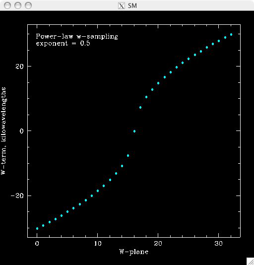
Type of the sampling in the w-space. The default is linear, which means that w-planes are set at equal distances in w. “powerlaw” means that w(plane) is proportional to pow(plane - (nwplanes-1)/2,exponent), where the exponent is a free parameter (must be given). “gaussian” means the distribution of w(plane) derived from truncated gaussian distribution in the range -wmax to wmax. This distribution is parameterized by a single parameter (must be given) nwplanes50, which means the number of w-planes (float is allowed) covering inner 50% of the -wmax to +wmax range of w-terms. The parameters A and sigma of the distribution w ~ A*(1-exp(-plane^2/(2*sigma^2)) are derived nwplanes50 by assuming that the first and the last w-planes always correspond to -wmax and +wmax respectively and the mid-range plane corresponds to w=0. Note, nwplanes50 should be a positive number not exceeding approximately 70% of the number of w-planes (it can be shown mathematically, that a distribution of this type with a larger concentration of w-planes does not exist). |
wsampling.exponent |
double |
none |
Exponent of the power law (can’t be 0) |
wsampling.nwplanes50 |
double |
none |
Parameter of the gaussian w-sampling. The number of w-planes covering inner 50% of the -wmax to +wmax value range of w-terms |
wsampling.export |
string |
“” |
If this parameter is not an empty string, the actual distribution of w-planes is exported. If the value of this parameter is equal to “log”, the distribution is exported into a usual log stream in a human readable form. Otherwise, the value of this parameter is interpreted as a file name, and the distribution is exported into this file in a machine readable form (three columns of data being the plane number, the resulting w-term and the plane number obtained as a result of the reverse conversion of the w-term into plane number) |
An example of the power-law distribution of the w-planes with exponent=0.5 is given below
Additional parameters for gridders with non-trivial convolution functions (WProject, MPIWProject, AWProject, AProjectWStack)
This section gives parameters understood by gridders based on non-trivial (i.e. not box or prolate spheroidal) convolution functions. For WProject gridder this section describes all remaining parameters in addition to those given above (common for all gridders and shared with WStack). Mosaicing gridders have further parameters. Note, AProjectWStack does not understand cutoff, variablesupport and offsetsupport parameters as the support size is defined by antenna aperture and is not searched.
Parameter |
Type |
Default |
Description |
|---|---|---|---|
cutoff |
double |
1e-3 |
Cutoff in determining support (note, relative cutoff must be greater than 0.0 and less than 1.0). The support is searched starting from the edge of the image inwards. As soon as the value of the convolution function exceeds cutoff times the peak (or just cutoff if absolute cutoff is used, see below), the distance from the centre (the largest value of two coordinates is used) becomes the support size. At the moment, we use a single value of the support, which is the largest across all family of convolution functions stored in the cache. The smaller the cutoff, the larger the support size and the more accurate gridding is performed. |
cutoff.absolute |
bool |
false |
If set to true, the cutoff value given by the parameter listed above is treated as an absolute cutoff value, rather than the fraction of the peak. This is an experimental feature. |
oversample |
int |
8 |
Oversampling factor. Convolution functions will be computed for this number of pixels per uv-cell. |
maxsupport |
int |
256 |
The largest allowed support size in pixels. The grid used to compute the convolution function (before the support is searched and the appropriate inner part of the grid is extracted) is initialised to have the size equal to the smallest of maxsupport and the image size. WProject uses maxsupport x maxsupport grid at the moment regardless of the image size. |
limitsupport |
int |
0 |
Upper limit of support. If the determined support size happens to be greater than this value, the support will be capped to this value. This limit is applied after the convolution functions are calculated, before an inner part of the grid is extracted to be stored in the convolution function cache. The default value of 0 indicates no limit is imposed. |
variablesupport |
bool |
false |
If true, the support will be searched separately for each convolution function. This can speed things up considerably, unless costs to search the support dominates. It was also found that when variable support is used, the algorithm is more sensitive to cutoff value. Too high cutoff value has a significant impact on the image quality if the variable support is used. |
offsetsupport |
bool |
false |
If true, an offset of the convolution function will be treated separately (the support will be defined by size and offset, which can be non-zero in general). This option reduces the memory footprint and speeds up greeting. It can only be used in conjunction with variablesupport=true |
tablename |
string |
“” |
Name of table to save convolution function into. This option largely exists for debugging to be able to inspect the non-trivial convolution function. It should not be normally used. If the string is empty (default) the convolution function is not saved. If the string is prefixed with “image:” (i.e. image:cfuncs.img), convolution functions corresponding to the first oversampling plane in both axes are stored in the image cube instead. Planes of the cube correspond to remaining planes (apart from oversampling) of the convolution function cache. In this mode, only reverse (and non-PSF) gridder stores its convolution functions. |
usedouble |
bool |
false |
If true, use double precision when calculating convolution functions in the WProject gridder. Double used to be the default, but there is little if any difference in the output with single precision. |
sharecf |
bool |
false |
If true, use a (static) cache for the convolution functions in the WProject gridder. This saves both time and memory, especially for large images and spectral line cubes. Tests show no significant changes in continuum imaging but small differences in spectral cubes, it is not clear yet if these are a problem. Feedback welcome |
cfrank |
integer |
1 |
The number of ranks/processes used to distribute the convolution function calculation. Note: this parameter is only used by the MPIWProject gridder. Also, it requires the variablesupport parameter to be set to true. |
Note, that an exception is raised if the support size found during the support search (before being capped by limitsupport) exceeds (number of pixels)/(2*oversample), Overflowing convolution function - increase maxSupport or decrease overSample. If the cutoff is too small, one may find it impossible to increase maxsupport (and image size) due to the amount of available memory. Decreasing oversampling factor compromises the quality of imaging. Therefore, in some cases making the cutoff larger is the only option to proceed with calculations on a given machine.
Parameters specific to mosaicing gridders (AWProject and AProjectWStack)
Mosaicing gridders (AWProject and AProjectWStack) are aware about the primary beam of the instrument and need additional parameters to define how it looks like (via illumination pattern), when it needs to be recomputed (tolerances) and how big the cache should be (maxfeeds and maxfields). Some parameters given in the two previous sections have different defaults and therefore are repeated here.
Parameter |
Type |
Default |
Description |
|---|---|---|---|
nwplanes |
int |
65 |
Number of w-planes. Number of w planes must be odd. See above |
maxsupport |
int |
128 |
The largest allowed support size in pixels. See above |
frequencydependent |
bool |
true |
If true, illumination pattern will be computed separately for each spectral channel |
spheroidaltaper |
bool |
false |
Whether or not to apply an image-domain spheroidal taper to the A-function during gridding and degridding (but not to the mosaicing weights). The taper function is the same as the anti-aliasing function used in the SphFunc, WProject and WStack gridders. |
spheroidalweightscutoff |
double |
0 |
If the spheroidalTaper is below this cutoff, set weights to zero. This stops the beam function being boosted at small and inaccurate taper values. A cutoff of 0.01 seems reasonable. |
maxfeeds |
int |
1 |
Maximum number of feeds allowed |
maxfields |
int |
1 |
Maximum number of fields allowed |
pointingtolerance |
string |
“0.0001rad” |
Pointing tolerance. Fields separated by a larger amount considered separate fields and the appropriate data are gridded with independent convolution functions. An exception is thrown if the number of fields exceeds maxfields. |
patolerance |
string |
“0.1rad” |
Parallactic angle tolerance |
freqtolerance |
string |
undefined |
Frequency tolerance (relative, threshold for df/f), negative value or word infinite mean the frequency axis is ignored |
illumination |
string |
“disk” |
Illumination model used with this gridder. Default is disk. Dish and blockage sizes are defined regardless of the model used (because all illumination models require them). Different models require different parameters. Current options: disk, ASKAP, ATCA, SKA_LOW. |
illumination.*Property* |
Additional parameters of illumination model (see below). Exact list of available properties depends on the illumination model used. Diameter and blockage (below) are given as gridder parameters. None of the extra properties are required for disk illumination. |
||
diameter |
double |
none |
Dish diameter in metres |
blockage |
double |
none |
Size of the central whole in metres |
ASKAP Illumination
This experimental pattern uses the holography based beam models to derive the average illumination pattern for an ASKAP antenna for a given beam number. The current beam models do not go quite far enough out for the illumination pattern to be calculated cleanly by FFT, so to avoid edge effects an additional taper can be applied beyond the beam cutoff level to force the beam pattern to zero at the edge. The only primarybeam type that can be specified here is the ASKAP_PB. See linmos (Linear Mosaic Applicator) for additional primarybeam parameters.
Parameter |
Type |
Default |
Description |
|---|---|---|---|
illumination.primarybeam |
string |
ASKAP_PB |
The only valid choice for the primary beam is ASKAP_PB which is the default |
illumination.primarybeam.ASKAP_PB.image |
string |
none |
FITS image file with 4/5 axes (see linmos). Specify the full filename (including .fits) |
illumination.primarybeam.ASKAP_PB.taper |
bool |
true |
Apply a gaussian taper to the beam model beyond the cutoff level specified in the next parameter |
illumination.primarybeam.ASKAP_PB.taper.cutoff |
double |
0.04 |
Cutoff level in the beam pattern beyond which the extra tapering is applied |
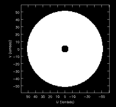
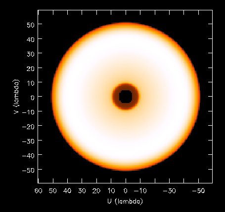
An example of the disk illumination for diameter 22m and blockage of 2m. For all illumination examples given below the frequency is assumed to be 1.4 GHz
ATCA Illumination
This illumination pattern allows to simulate additional effects (e.g. feed leg shadows, tapering) on top of the disk illumination. With the tapering, feedlegs and wedges parameters set to false, this illumination pattern is equivalent to disk (blockage and diameter are given as parameters of the gridder, rather than as parameters of illumination pattern because they apply to both currently implemented types of illumination). ATCA illumination has the following parameters:
Parameter |
Type |
Default |
Description |
|---|---|---|---|
illumination.tapering |
bool |
true |
This option switches on Jamesian tapering (i.e. imperfect illumination). The parameters of the taper are hard coded at the moment and correspond to the ATCA model. |
illumination.tapering.defocusing |
string |
0rad |
Only valid if illumination.tapering = true. An additional phase term is applied to the Jamesian illumination.The phase varies quadratically with radius from 0 at the dish centre to the value given in this parameter at the edge. |
illumination.feedlegs |
bool |
true |
If true, feed leg shadows are simulated (i.e. partial blockage of the radiation by the struts supporting the subreflector/focus cabin) |
illumination.feedlegs.width |
string |
1.8m |
Only applicable if illumination.feedlegs = true. The width of the shadows in the absolute units (as dish diameter is also given in the absolute units) |
illumination.feedlegs.rotation |
string |
45deg |
Only applicable if illumination.feedlegs = true. The angle the shadows are rotated. It corresponds to installation angle of the actual feeds. If this parameter is zero, the shadows go in the u and v direction. At ATCA the feeds are installed at 45 deg angle, which is the default. |
illumination.feedlegs.shadowing |
double |
0.75 |
Only applicable if illumination.feedlegs = true. This parameter describes how transparent feed leg shadows are. Zero indicates a total blockage, one a total transparency. |
illumination.feedlegs.wedges |
bool |
true |
Only applicable if illumination.feedlegs = true. If this parameter is set to true, shadow wedges resulted from multiple reflections (e.g. in the Cassegrain design). The wedges are simulated as triangular shadows on top of the feed leg shadows (adding more opacity) |
illumination.feedlegs.wedges.shadowing |
vector<double> |
[0.6,0.5] |
Only valid if illumination.feedlegs.wedges = true. Transparency factors for wedges corresponding to the horizontal and vertical (without rotation) feed legs. Zero indicates a total blockage, one is for total transparency.This opacities are applied linearly on top of the normal feed leg shadowing factor. Either one or two values could be given. If one value is given it corresponds to all wedges. |
illumination.feedlegs.wedges.angle |
string |
15deg |
Only valid if illumination.feedlegs.wedges = true. Opening angle for all triangular wedges. |
illumination.feedlegs.wedges.startradius |
string |
3.5m |
Only valid if illumination.feedlegs.wedges = true. The radius of the vertex for all triangular wedges. |
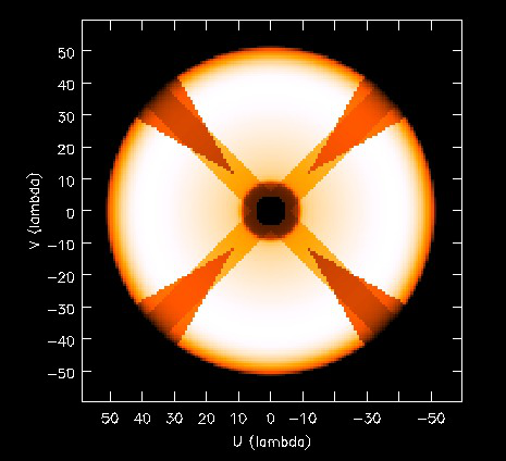
Example of the ATCA illumination model created with default parameters (i.e. with feed legs and wedges enabled)
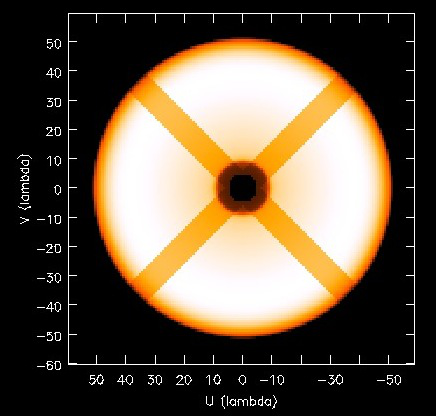
Example of the ATCA illumination model without wedges and with default values of other parameters.
Example of the ATCA illumination model without feedlegs (and wedges). All other parameters have default values. This case is essentially a disk with tapering.
Examples
Simple example:
Cimager.gridder                                 = WProject
Cimager.gridder.WProject.wmax                   = 15000
Cimager.gridder.WProject.nwplanes               = 129
Cimager.gridder.WProject.oversample             = 8
Cimager.gridder.WProject.maxsupport             = 1024
Cimager.gridder.WProject.tablename              = WProject.tab
Example with ATCA illumination pattern:
Cimager.gridder                                   = AProjectWStack
Cimager.gridder.alldatapsf                        = true
Cimager.gridder.padding                           = 1
Cimager.gridder.AProjectWStack.wmax               = 1.0
Cimager.gridder.AProjectWStack.diameter           = 22m
Cimager.gridder.AProjectWStack.blockage           = 3.6m
Cimager.gridder.AProjectWStack.nwplanes           = 1
Cimager.gridder.AProjectWStack.oversample         = 16
Cimager.gridder.AProjectWStack.cutoff             = 0.001
Cimager.gridder.AProjectWStack.maxfeeds           = 1
Cimager.gridder.AProjectWStack.maxfields          = 1
Cimager.gridder.AProjectWStack.maxsupport         = 1024
Cimager.gridder.AProjectWStack.frequencydependent = true

Cimager.gridder.AProjectWStack.illumination                             = ATCA
Cimager.gridder.AProjectWStack.illumination.tapering                    = true
Cimager.gridder.AProjectWStack.illumination.tapering.defocusing         = 0deg
Cimager.gridder.AProjectWStack.illumination.feedlegs                    = true
Cimager.gridder.AProjectWStack.illumination.feedlegs.width              = 1.0m
Cimager.gridder.AProjectWStack.illumination.feedlegs.rotation           = 45deg
Cimager.gridder.AProjectWStack.illumination.feedlegs.shadowing          = 0.75
Cimager.gridder.AProjectWStack.illumination.feedlegs.wedges             = true
Cimager.gridder.AProjectWStack.illumination.feedlegs.wedges.shadowing   = [0.6,0.5]
Cimager.gridder.AProjectWStack.illumination.feedlegs.wedges.angle       = 15deg
Cimager.gridder.AProjectWStack.illumination.feedlegs.wedges.startradius = 3.5m