Caption for AT Sensitivity Plot
(see also the update at the end of this document)
Peter Hall, 18 March 1996.
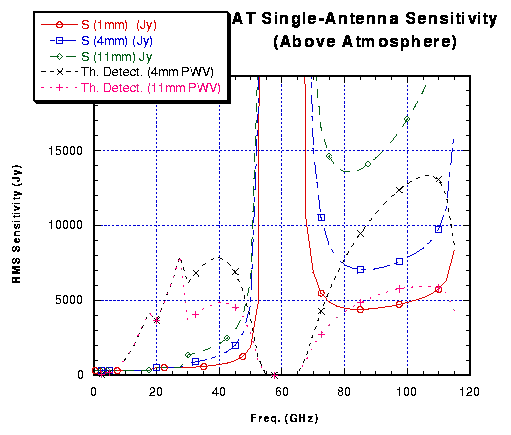
I have compiled this plot as an indicator of AT system performance. I've had to make a few assumptions but, nonetheless, it illustrates orders of magnitudes and functional forms rather well. Note that it refers to one antenna only - either Mopra or one element of the ATCA.
My method has been to take the atmospheric transmission curves supplied by Michael Burton, derive corresponding tau values, assume receiver noise temperature values for various bands, then derive an above-atmosphere system temperature using T' = Tr.exp(tau) + T (exp(tau)-1). In this expression tau is the opacity, Tr is the receiver temperature, T~290K (see, e.g. "Interferometry and Synthesis in Radio Astronomy" by Thompson, Moran & Swenson, p. 419 for more explanation). I have then converted to equivalent flux using S = 2k.T'/Ap.e where k is Boltzmann's constant, Ap is the physical area of the antenna and e is the aperture efficiency. Finally, to illustrate the relative detactability of thermal line emission, I have plotted frequency^2.5 curves divided by S, the quotients being scaled by an arbitrary multiplier of 1000 to make it appropriate to the existing ordinates.
Here are my assumptions:
- No detailed atmospheric modelling below 30 GHz (i.e., no 22 GHz atmospheric resonance).
- Antenna physical diameters of 22m to 50 GHz and 15m above 70 GHz, with a linear decrease between these limits.
- Antenna surface errors in the inner 15m section of 150 micron rms, giving high frequency efficiencies as plotted on my graph in these web pages. For the sake of discussion, I've left this surface accuracy in place for the full-diameter antenna. This means that my efficiencies turn out to be 0.59, 0.58, 0.56, 0.54 at 20, 30, 40 and 50 GHz.
- Receiver temperatures: 25K to 17.5 GHz, 40K to 65 GHz, then 100K to 115 GHz.
The discontinuities in the curves at 17.5 GHz and 30 GHz are due to changes in Tr and the switch to detailed atmospheric modelling.
Note: Low values of S are good; high values of detectability (which is really signal-to-noise) are also good.
UPDATE (29 January 1997)!!!
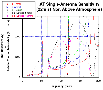
This new graph is derived in the same manner as the earlier version . The difference is that the antenna diameter is now assumed to be 22 m, in line with the final MNRF decision. The antenna surface inaccuracy is taken as 150um across the entire reflector. An updated atmospheric model (courtesy of Michael Bremer, IRAM) has been used. The sensitivity advantages of a 3 or 3.5 mm upgrade are clear and, despite the legitimate concerns about operation at 115 GHz, these plots reinforce the importance of keeping that option alive.